


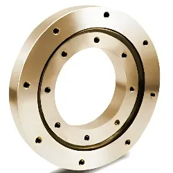

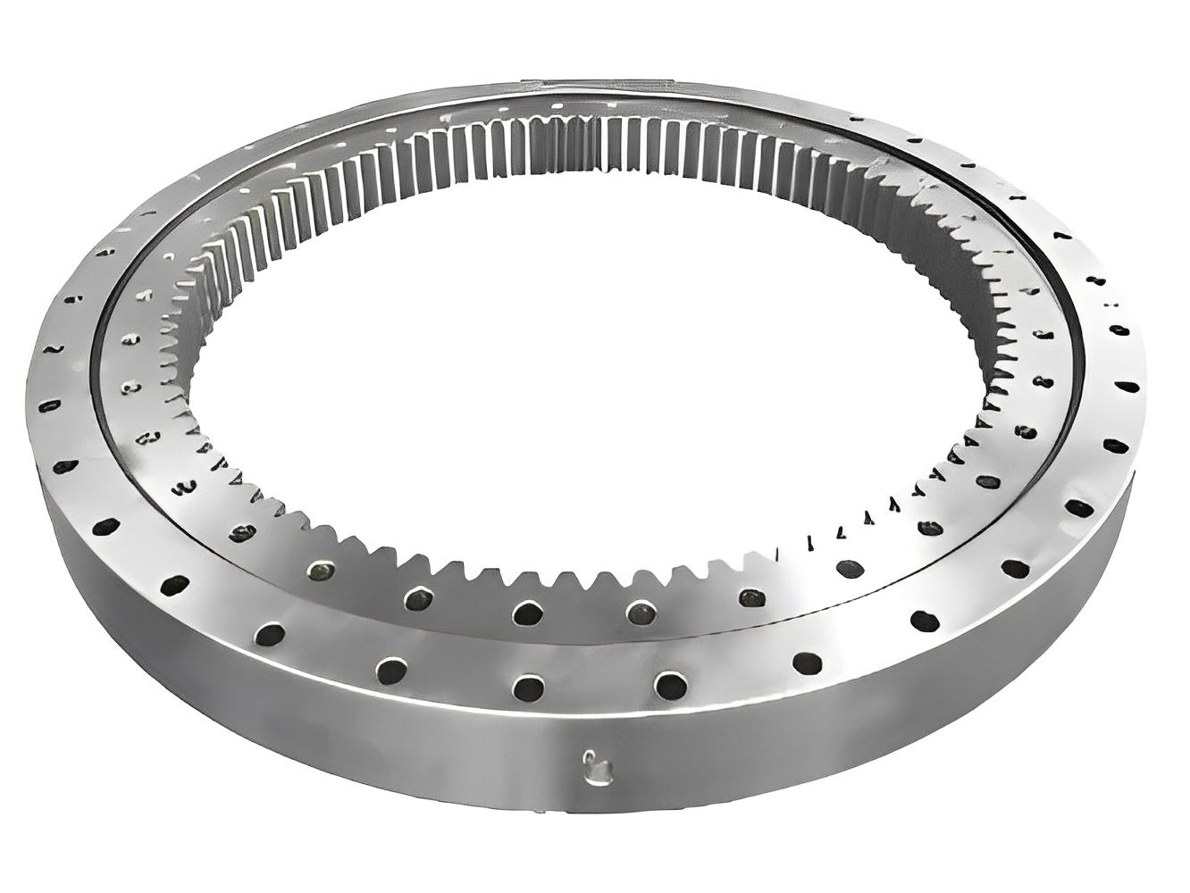
Compact structure, light weight and high manufacturing accuracy;
The product has small assembly clearance and high requirements for installation accuracy;
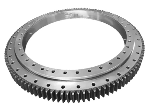
Rollers are arranged 1:1 cross-arranged;
At the same time, bear axial force, tilt torque and large radial force;
Applied to construction robots, automation, medical industries, precision instruments, etc.;
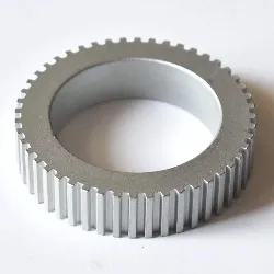
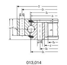
Single row four-point contact ball rotary support (Series 01) structural parameters---internal tooth type
|
No. of bearing curve chart |
Model D mm |
Overall dimensions |
Installation Dimensions |
|||||||
|
De mm |
D mm |
d mm |
H mm |
D mm |
D mm |
n |
φ mm |
M mm |
||
|
1 |
013.20.400.601 |
300 |
475 |
|
55 |
448 |
352 |
16 |
13.5 |
12 |
|
2 |
013.20.450.601 |
345 |
531 |
|
55 |
500 |
400 |
16 |
15.5 |
14 |
|
3 |
013.30.500.001 |
367 |
602 |
398 |
80 |
566 |
434 |
20 |
18 |
16 |
|
014.30.500.001 |
368.4 |
|||||||||
|
4 |
013.20.560.601 |
450 |
641 |
|
55 |
610 |
510 |
20 |
15.5 |
14 |
|
5 |
013.30.560.001 |
427 |
662 |
458 |
80 |
626 |
494 |
20 |
18 |
16 |
|
014.30.560.001 |
428.4 |
|||||||||
|
7 |
013.30.630.001 |
494.4 |
732 |
528 |
80 |
696 |
564 |
twenty four |
18 |
16 |
|
014.30.630.001 |
491.2 |
|||||||||
|
8 |
013.20.710.601 |
594 |
797 |
|
55 |
762 |
658 |
twenty four |
18 |
16 |
|
9 |
013.30.710.001 |
572.4 |
812 |
608 |
80 |
776 |
644 |
twenty four |
18 |
16 |
|
014.30.710.001 |
571.2 |
|||||||||
|
13 |
013.40.800.001 |
635.2 |
922 |
678 |
100 |
878 |
722 |
30 |
twenty two |
20 |
|
014.40.800.001 |
634 |
|||||||||
|
48 |
013.25.886.601 |
752 |
980 |
|
63 |
944 |
827 |
36 |
18 |
16 |
|
15 |
013.40.900.001 |
739.2 |
1022 |
778 |
100 |
978 |
822 |
30 |
twenty two |
20 |
|
014.40.900.001 |
734 |
|||||||||
|
19 |
013.40.1000.001 |
824 |
1122 |
878 |
100 |
1078 |
922 |
36 |
twenty two |
20 |
|
014.40.1000.001 |
820.8 |
|||||||||
|
49 |
013.25.1077.601 |
930 |
1169 |
|
63 |
1134 |
1017 |
36 |
18 |
16 |
|
50 |
013.30.1120.601 |
960 |
1232 |
|
79 |
1188 |
1052 |
36 |
twenty two |
20 |
|
twenty two |
013.40.1120.001 |
944 |
1242 |
998 |
100 |
1198 |
1042 |
36 |
twenty two |
20 |
|
014.40.1120.001 |
940.8 |
|||||||||
|
51 |
013.30.1250.601 |
1090 |
1362 |
|
79 |
1318 |
1182 |
40 |
twenty two |
20 |
|
No. of bearing curve chart |
Model D mm |
Overall dimensions |
Installation Dimensions |
|||||||
|
De mm |
D mm |
d mm |
H mm |
D mm |
D mm |
n |
Φ mm |
M mm |
||
|
1 |
023.25.500.002 |
357 |
616 |
384 |
106 |
580 |
420 |
20 |
18 |
16 |
|
024.25.500.002 |
350.4 |
|||||||||
|
2 |
023.25.560.002 |
417 |
676 |
444 |
106 |
640 |
480 |
20 |
18 |
16 |
|
024.25.560.002 |
410.4 |
|||||||||
|
3 |
023.25.630.002 |
482.4 |
746 |
514 |
106 |
710 |
550 |
twenty four |
18 |
16 |
|
024.25.630.002 |
475.2 |
|||||||||
|
4 |
023.25.710.002 |
560.4 |
826 |
594 |
106 |
790 |
630 |
twenty four |
18 |
16 |
|
024.25.710.002 |
555.2 |
|||||||||
|
5 |
023.30.800.002 |
619.2 |
942 |
658 |
124 |
898 |
702 |
30 |
twenty two |
20 |
|
024.30.800.002 |
614 |
|||||||||
|
6 |
023.30.900.002 |
715.2 |
1042 |
758 |
124 |
998 |
802 |
30 |
twenty two |
20 |
|
024.30.900.002 |
714 |
|||||||||
|
7 |
023.30.1000.002 |
814 |
1142 |
858 |
124 |
1098 |
902 |
36 |
twenty two |
20 |
|
024.30.1000.002 |
796.8 |
|||||||||
|
8 |
023.30.1120.002 |
924 |
1262 |
978 |
124 |
1218 |
1022 |
36 |
twenty two |
20 |
|
024.30.1120.002 |
916.8 |
|||||||||
|
9 |
023.40.1250.002 |
1012.8 |
1426 |
1074 |
160 |
1374 |
1126 |
40 |
26 |
twenty four |
|
024.40.1250.002 |
1013.6 |
|||||||||
|
10 |
023.40.1400.002 |
1156.8 |
1576 |
1224 |
160 |
1524 |
1272 |
40 |
26 |
twenty four |
|
024.40.1400.002 |
1153.6 |
|||||||||
|
No. of bearing curve chart |
Model D mm |
Overall dimensions |
Installation Dimensions |
|||||||
|
De mm |
D mm |
d mm |
H mm |
D mm |
D mm |
n |
φ mm |
M mm |
||
|
11 |
023.40.1600.002 |
1349.6 |
1776 |
1424 |
160 |
1724 |
1476 |
45 |
26 |
twenty four |
|
024.40.1600.002 |
1350.4 |
|||||||||
|
12 |
023.40.1800.002 |
1545.6 |
1976 |
1624 |
160 |
1924 |
1676 |
45 |
26 |
twenty four |
|
024.40.1800.002 |
1542.4 |
|||||||||
|
13 |
023.50.2000.002 |
1702.4 |
2215 |
1785 |
190 |
2149 |
1851 |
48 |
33 |
30 |
|
024.50.2000.002 |
1699.2 |
|||||||||
|
14 |
023.50.2240.002 |
1942.4 |
2455 |
2025 |
190 |
2389 |
2091 |
48 |
33 |
30 |
|
024.50.2240.002 |
1933.2 |
|||||||||
|
15 |
023.50.2500.002 |
2203.2 |
2715 |
2285 |
190 |
2649 |
2351 |
56 |
33 |
30 |
|
024.50.2500.002 |
2188 |
|||||||||
|
16 |
023.50.2800.002 |
2491.2 |
3015 |
2585 |
190 |
2949 |
2651 |
56 |
33 |
30 |
|
024.50.2800.002 |
2488 |
|||||||||
|
17 |
023.60.3150.002 |
2768 |
3428 |
2872 |
226 |
3338 |
2962 |
56 |
45 |
42 |
|
024.60.3150.002 |
2758.8 |
|||||||||
|
18 |
023.60.3550.002 |
3168 |
3828 |
3272 |
226 |
3738 |
3362 |
56 |
45 |
42 |
|
024.60.3550.002 |
3176.8 |
|||||||||
|
19 |
023.60.4000.002 |
3616.8 |
4278 |
3722 |
226 |
4188 |
3812 |
60 |
45 |
42 |
|
024.60.4000.002 |
3610 |
|||||||||
|
20 |
023.60.4500.002 |
4122.8 |
4778 |
4222 |
226 |
4688 |
4312 |
60 |
45 |
42 |
|
024.60.4500.002 |
4110 |
|||||||||