


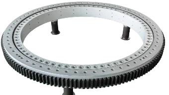
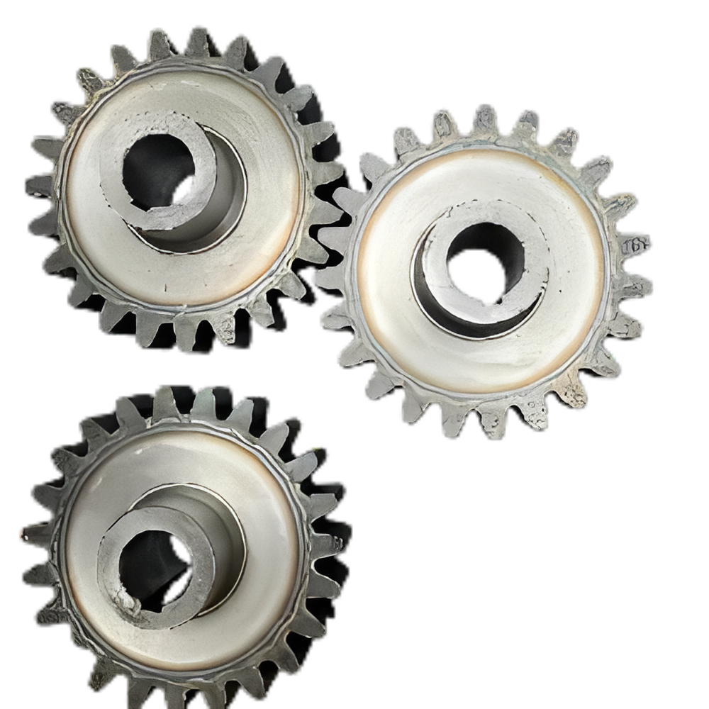
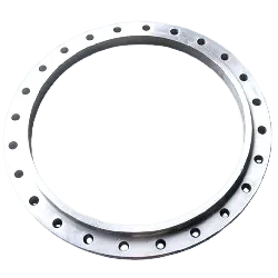


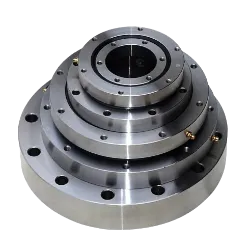
Light and Thin Equipment Support
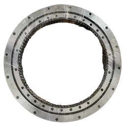
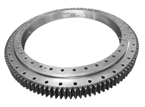
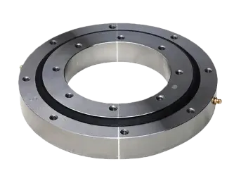
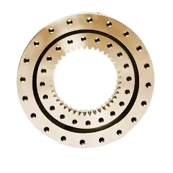
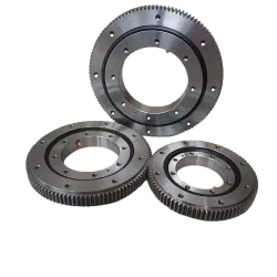
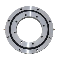
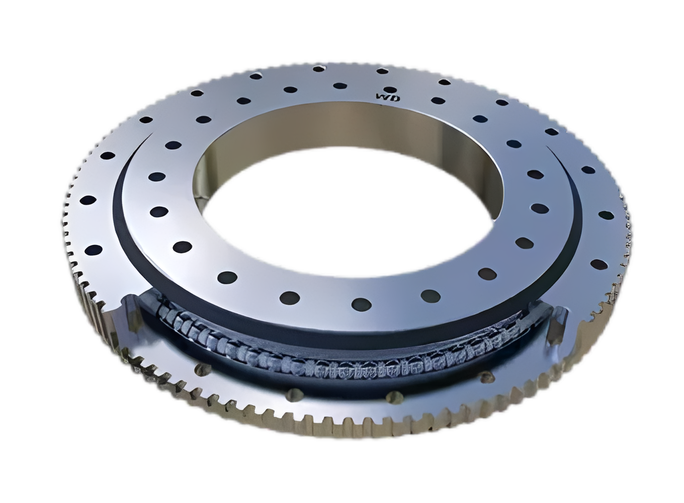
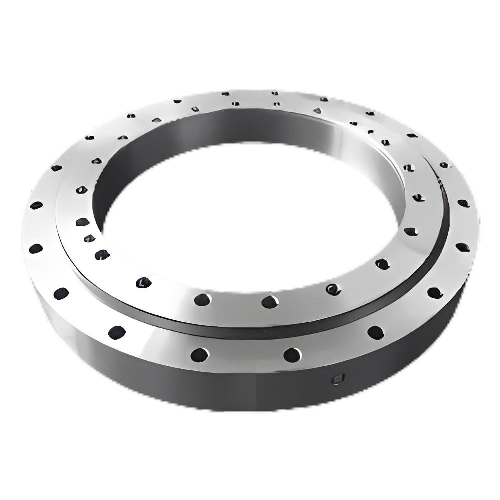
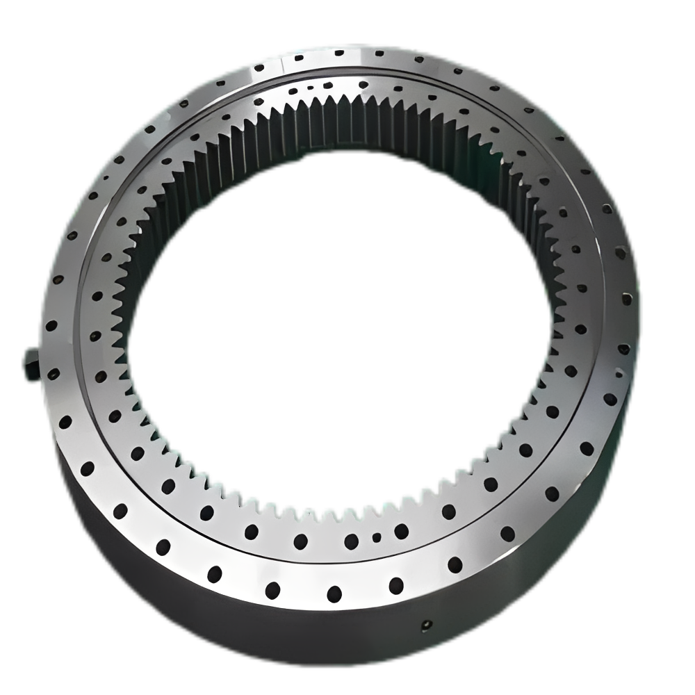
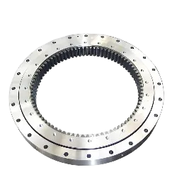
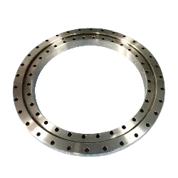
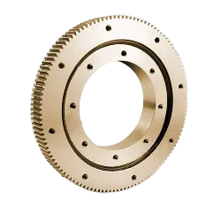
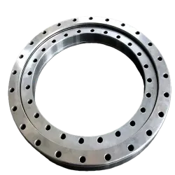
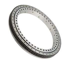
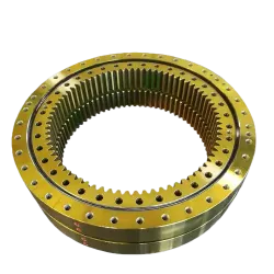
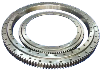
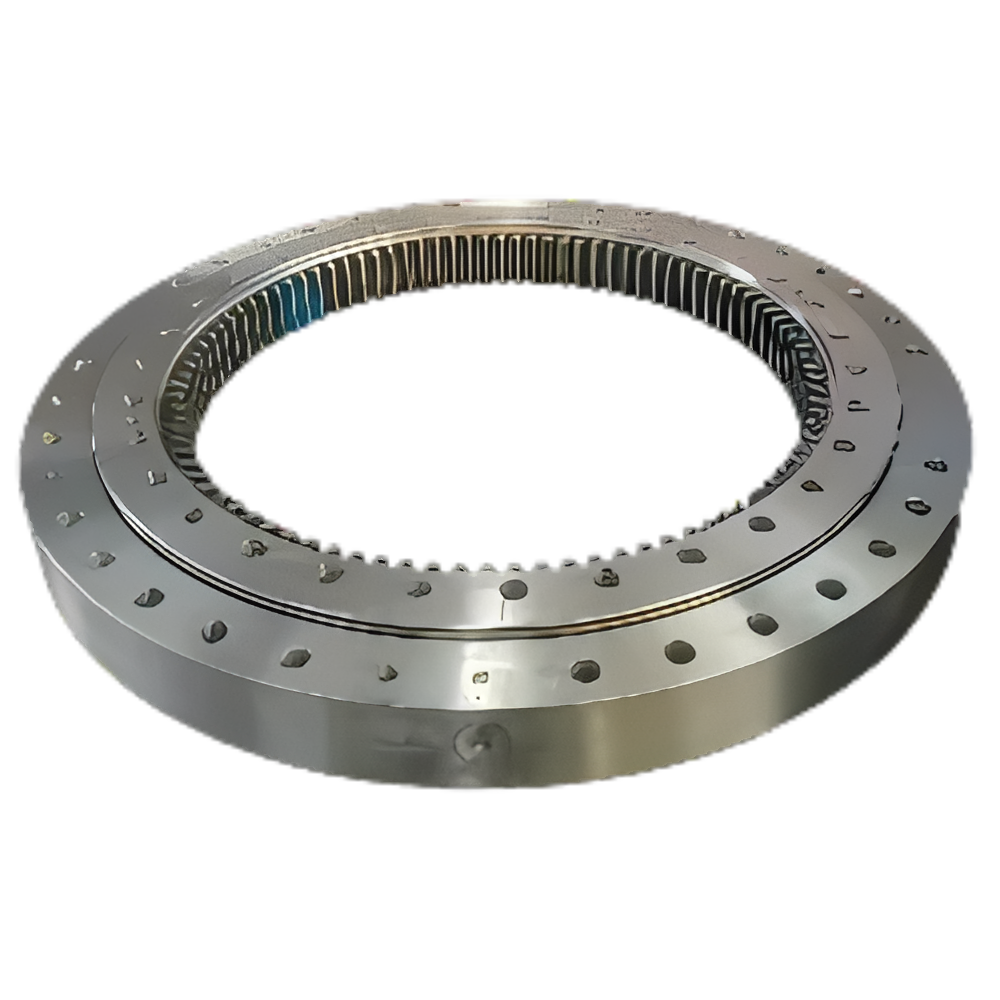
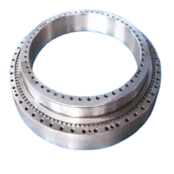
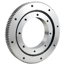
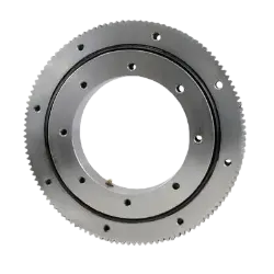
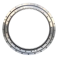
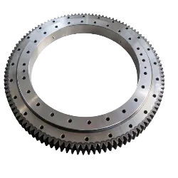
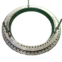
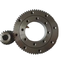
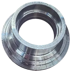
Custom Slewing Bearing. Light Slewing Bearing Has the Characteristics of Light Weight, Flexible Rotation, Convenient Installation, Etc. It Can Be Widely Used in Granulator, Wood Turning Machine, Packaging Machine, Canning Machine, Semi-automatic Robot, Injection Molding Machine, Dryer, Rotary Kiln, Drive Machine and Other Rotatable Equipment Accessories.
Contact Us
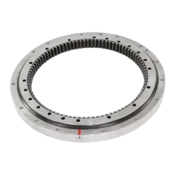
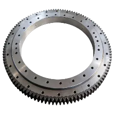
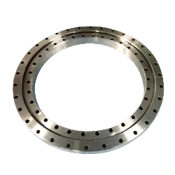
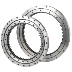
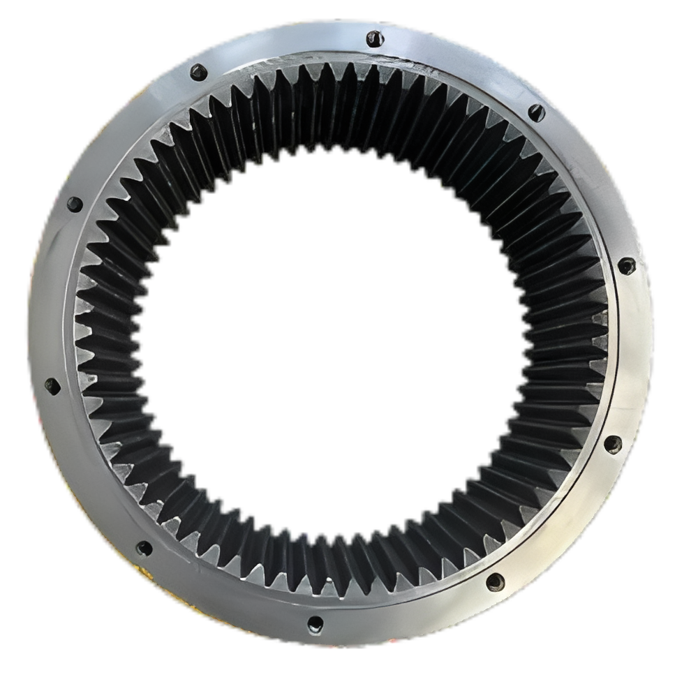
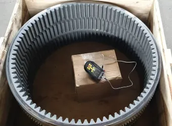
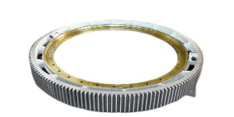
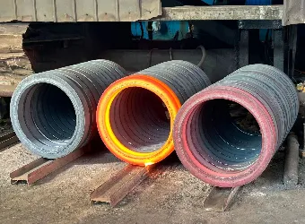
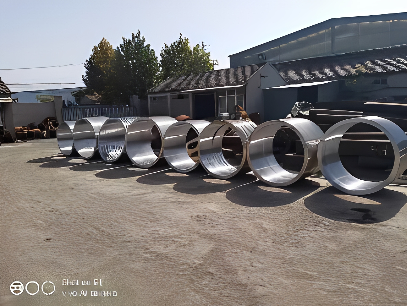
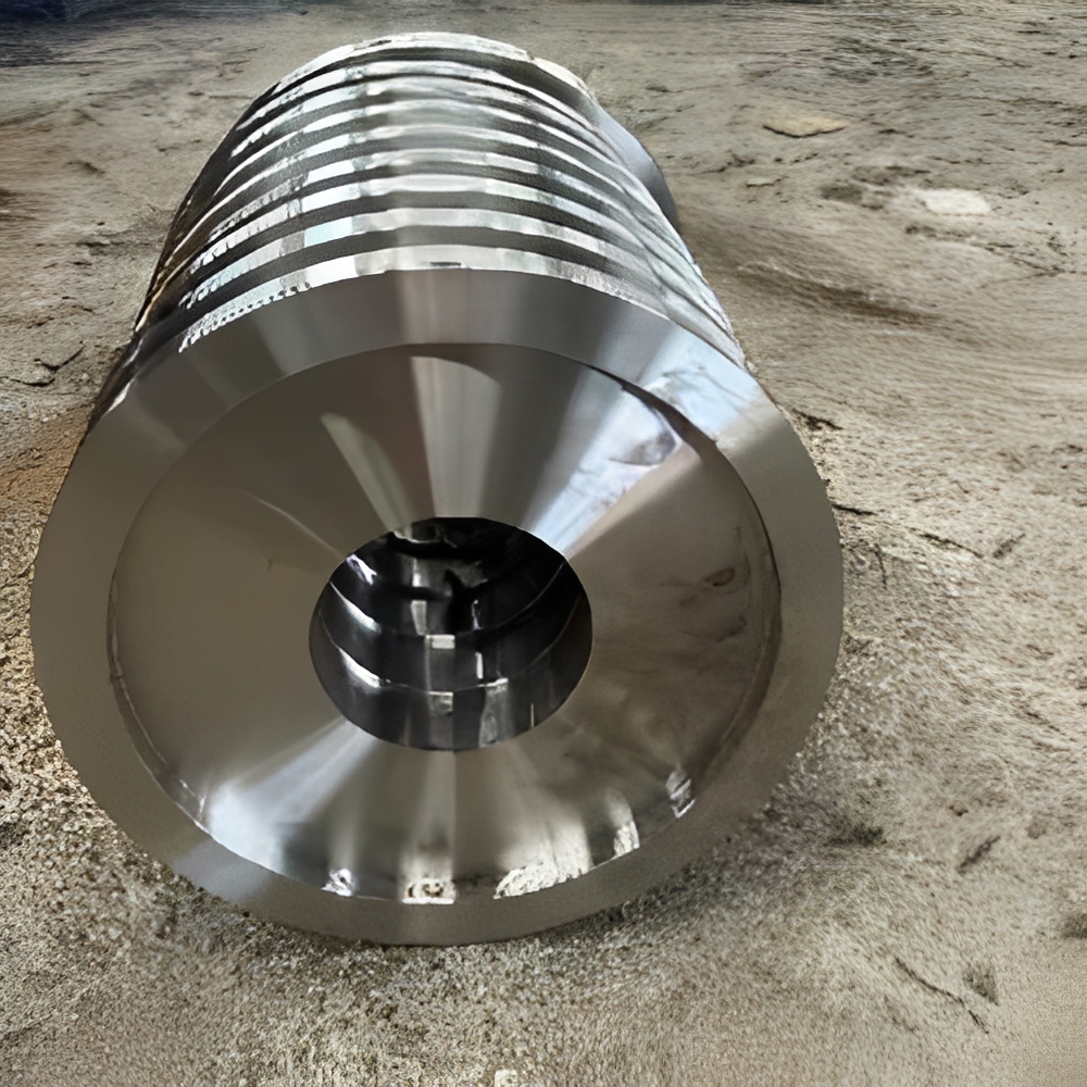
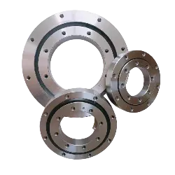
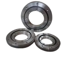
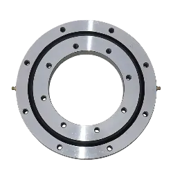
Product Description
Note
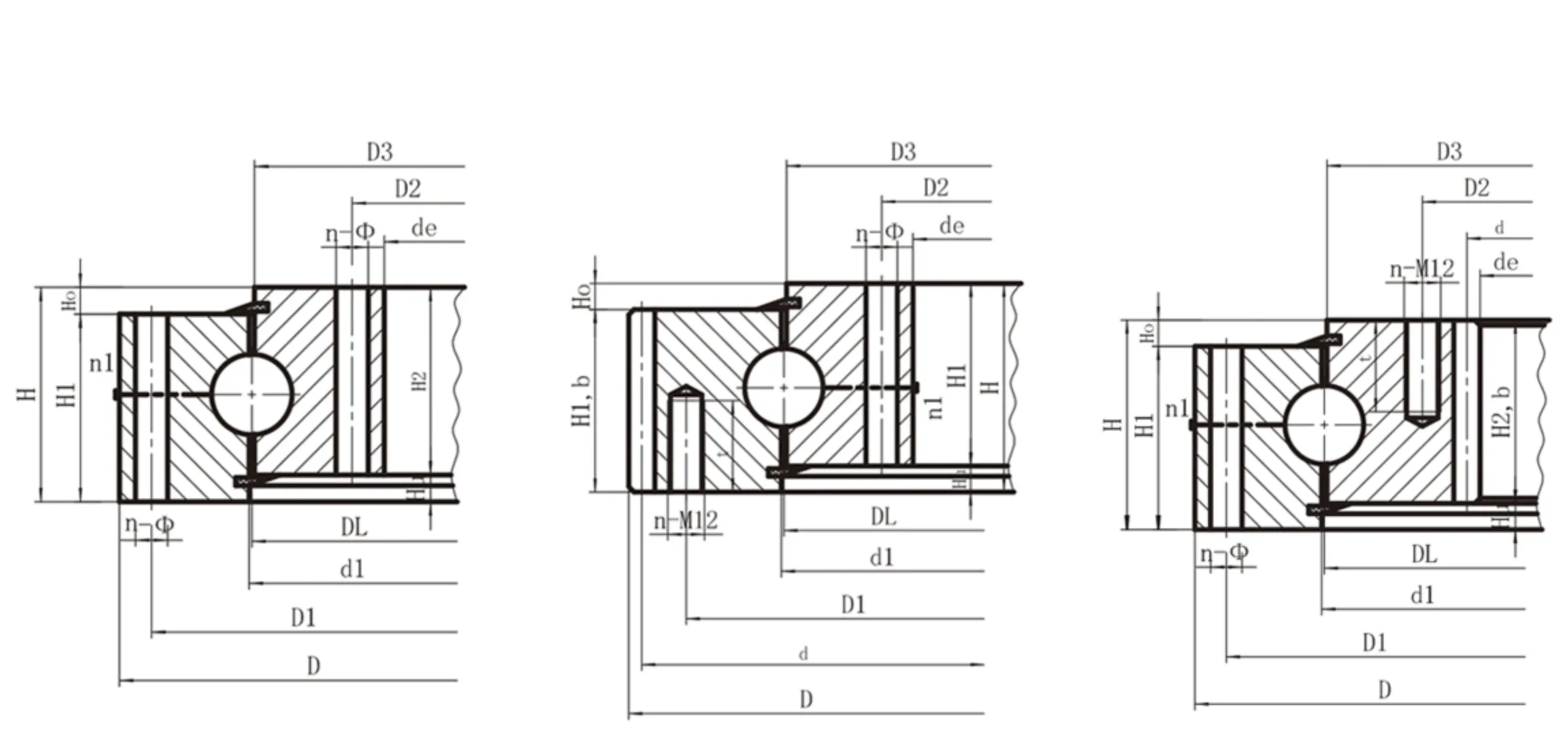
1, n1 for Lubricating Oil Hole Count. Oil Cup M10x1JB/T7940.1~JB/T7940.
2 , you Can Specify the Position of the Oil Hole According to the Application, n-Φ Can Be Changed to Tapping Hole, Thread Diameter M, Thread Depth 2M
3, Table Internal Gear Force of Periphery Is the Maximum Force of Periphery, Rated Force of Periphery1/2.
4," K"Is the Top Cutting Coefficient.
5. the Specifications in This Sample Are Standard Products., the Inner and Outer Diameter Are Free Tolerance. If the Host and Slewing Bearing Have Cooperation Requirements, Please in the Contract Or Contract Attachment( such as Technical Agreement) the Matching Size and Precision Are Indicated in.
6. the Regular Products Listed in the Table Are Listed in Our Company. If You Have Any Other Special Requirements, Please Contact Our Company.
| Model | weight | Overall Dimensions | Installation Dimensions | Structural Dimensions | Gear Parameters | Gear Tangential Force | Axial Clearance | Radial Clearance | |||||||||||||||||
| D | de | H | D1 | D2 | na | Φ | M | T | D3 | d1 | H1 | H2 | Hu | Ho | D | M | Z | k.M | B | Allowable Tangential Force | Maximum Allowable Tangential Force | ||||
| YQ-061.20.0414 | 31 | 504 | 342 | 56 | 455 | 368 | 20/24 | 13.5 | 12 | 20 | 412.5 | 415.5 | 45.5 | 45.5 | 10.5 | 10.5 | 495 | 5 | 99 | -0.5 | 45.5 | 11.75 | 23.5 | ≤ 0.28 | ≤ 0.24 |
| YQ-061.20.0544 | 43 | 640.8 | 472 | 56 | 585 | 498 | 28/32 | 13.5 | 12 | 20 | 542.5 | 545.5 | 45.5 | 45.5 | 10.5 | 10.5 | 630 | 6 | 105 | -0.6 | 45.5 | 14.2 | 28.4 | ≤ 0.30 | ≤ 0.26 |
| YQ-061.20.0644 | 52 | 742.8 | 572 | 56 | 685 | 598 | 32/36 | 13.5 | 12 | 20 | 642.5 | 645.5 | 45.5 | 45.5 | 10.5 | 10.5 | 732 | 6 | 122 | -0.6 | 45.5 | 14.2 | 28.4 | ≤ 0.30 | ≤ 0.26 |
| YQ-061.20.0744 | 59 | 838.8 | 672 | 56 | 785 | 698 | 36/40 | 13.5 | 12 | 20 | 742.5 | 745.5 | 45.5 | 45.5 | 10.5 | 10.5 | 858 | 6 | 138 | -0.6 | 45.5 | 14.2 | 28.4 | ≤ 0.30 | ≤ 0.26 |
| YQ-061.20.0844 | 71 | 950.4 | 772 | 56 | 885 | 798 | 38/40 | 13.5 | 12 | 20 | 842.5 | 845.5 | 45.5 | 45.5 | 10.5 | 10.5 | 936 | 8 | 117 | -0.8 | 45.5 | 18.93 | 37.86 | ≤ 0.30 | ≤ 0.26 |
| YQ-061.20.0944 | 77 | 1046.4 | 872 | 56 | 985 | 898 | 40/44 | 13.5 | 12 | 20 | 942.5 | 945.5 | 45.5 | 45.5 | 10.5 | 10.5 | 1032 | 8 | 129 | -0.8 | 45.5 | 18.93 | 37.86 | ≤ 0.30 | ≤ 0.26 |
| YQ-061.20.1094 | 91 | 1198.4 | 1022 | 56 | 1135 | 1048 | 44/48 | 13.5 | 12 | 20 | 1092.5 | 1095.5 | 45.5 | 45.5 | 10.5 | 10.5 | 1184 | 8 | 148 | -0.8 | 45.5 | 18.93 | 37.86 | ≤ 0.30 | ≤ 0.26 |
| Model | weight | Overall Dimensions | Installation Dimensions | Structural Dimensions | Gear Parameters | Allowable Tangential Force | Maximum Allowable Tangential Force | Axial Clearance | Radial Clearance | ||||||||||||||||||
| D | de | H | D1 | D2 | na | Φ/M | NI | Φ/M | T | n1 | D3 | d1 | A | C | Hu | Ho | D | M | Z | B | k.M | ||||||
| YQ-231.20.0414 | 29.0 | 504 | 304 | 56 | 455 | 332 | 10 | M12 | 24 | 18 | 20 | 4 | 412.5 | 415.5 | 375 | 10.5 | 10.5 | 495 | 5 | 99 | 45.5 | -0.5 | 11.75 | 23.50 | ≤ 0.5 | ≤ 0.5 | |
| YQ-231.20.0544 | 39.2 | 640.8 | 434 | 56 | 585 | 462 | 14 | M12 | 28 | 18 | 20 | 4 | 542.5 | 545.5 | 505 | 10.5 | 10.5 | 630 | 6 | 105 | 45.5 | -0.6 | 14.2 | 28.40 | ≤ 0.5 | ≤ 0.5 | |
| YQ-231.20.0644 | 47.2 | 742.8 | 534 | 56 | 685 | 562 | 16 | M12 | 32 | 18 | 20 | 4 | 642.5 | 645.5 | 605 | 10.5 | 10.5 | 732 | 6 | 122 | 45.5 | -0.6 | 14.2 | 28.40 | ≤ 0.5 | ≤ 0.5 | |
| YQ-231.20.0744 | 53.1 | 838.8 | 634 | 56 | 785 | 662 | 18 | M12 | 32 | 18 | 20 | 4 | 742.5 | 745.5 | 705 | 10.5 | 10.5 | 828 | 6 | 138 | 45.5 | -0.6 | 14.2 | 28.40 | ≤ 0.5 | ≤ 0.5 | |
| YQ-231.20.0844 | 64.7 | 950.4 | 734 | 56 | 885 | 762 | 18 | M12 | 36 | 18 | 20 | 4 | 842.5 | 845.5 | 805 | 10.5 | 10.5 | 936 | 8 | 117 | 45.5 | -0.8 | 18.93 | 37.86 | ≤ 0.5 | ≤ 0.5 | |
| YQ-231.20.0944 | 69.1 | 1046.4 | 834 | 56 | 985 | 862 | 20 | M12 | 40 | 18 | 20 | 4 | 942.5 | 945.5 | 905 | 10.5 | 10.5 | 1032 | 8 | 129 | 45.5 | -0.8 | 18.93 | 37.86 | ≤ 0.5 | ≤ 0.5 | |
| YQ-231.20.1094 | 82.5 | 1198.4 | 984 | 56 | 1135 | 1012 | 22 | M12 | 40 | 18 | 20 | 4 | 1092.5 | 1095.5 | 1055 | 10.5 | 10.5 | 1184 | 8 | 148 | 45.5 | -0.8 | 18.93 | 37.86 | ≤ 0.5 | ≤ 0.5 | |
| NO. | Basic Model | Overall Dimensions | Installation Dimensions | Structure Size | Gear Parameters | Parameters of Internal Gears | Parameters of External Gears | |||||||||||||||
| Non-gear Type D L(Mm) | External Gear Type D L(Mm) | Internal Gear Type D L(Mm) | D | D | H | D₁ | D₂ | N | Φ | n₁ | D₃ | d₁ | H₁ | H | B | X | M | De | Z | De | Z | |
| MM | MM | MM | MM | MM | MM | |||||||||||||||||
| 1 | 010.20.200 | 011.20.200 | - | 280 | 120 | 60 | 248 | 152 | 12 | 16 | 2 | 201 | 199 | 50 | 10 | 40 | 0 | 3 | 300 | 98 | - | - |
| 2 | 010.20.224 | 011.20.224 | - | 304 | 144 | 60 | 272 | 176 | 12 | 16 | 2 | 225 | 223 | 50 | 10 | 40 | 0 | 3 | 321 | 105 | - | - |
| 3 | 010.20.250 | 011.20.250 | - | 330 | 170 | 60 | 298 | 202 | 18 | 16 | 2 | 251 | 249 | 50 | 10 | 40 | 0 | 4 | 352 | 86 | - | - |
| 4 | 010.20.280 | 011.20.280 | - | 360 | 200 | 60 | 328 | 232 | 18 | 16 | 2 | 281 | 279 | 50 | 10 | 40 | 0 | 4 | 384 | 94 | - | - |
| 5 | 010.25.315 | 011.25.315 | 013.25.315 | 408 | 222 | 70 | 372 | 258 | 20 | 18 | 2 | 316 | 314 | 60 | 10 | 50 | 0 | 5 | 435 | 85 | 190 | 40 |
| 6 | 010.25.355 | 011.25.355 | 013.25.355 | 448 | 262 | 70 | 412 | 298 | 20 | 18 | 2 | 356 | 354 | 60 | 10 | 50 | 0 | 5 | 475 | 93 | 235 | 49 |
| 7 | 010.25.400 | 011.25.400 | 013.25.400 | 493 | 307 | 70 | 457 | 343 | 24 | 18 | 2 | 401 | 399 | 60 | 10 | 50 | 0 | 6 | 528 | 86 | 276 | 48 |
| 8 | 010.25.450 | 011.25.450 | 013.25.450 | 543 | 357 | 70 | 507 | 393 | 24 | 18 | 2 | 451 | 449 | 60 | 10 | 50 | 0 | 6 | 576 | 94 | 324 | 56 |