


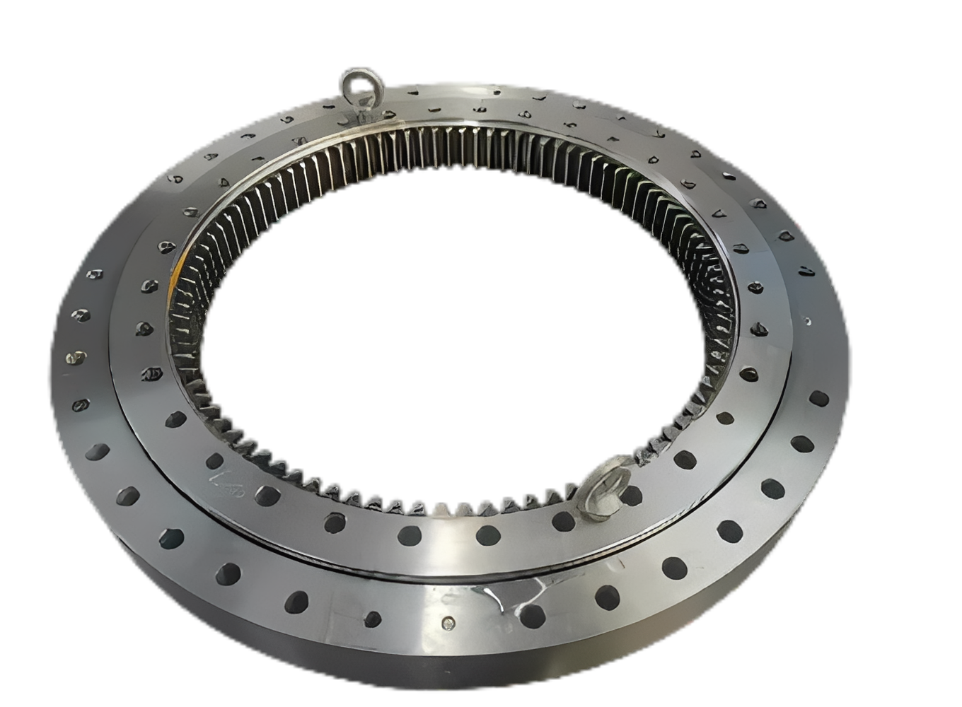
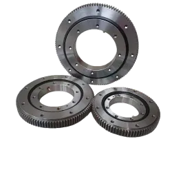
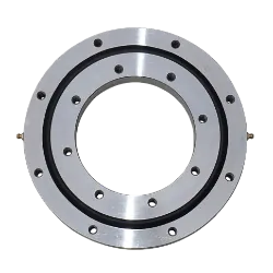
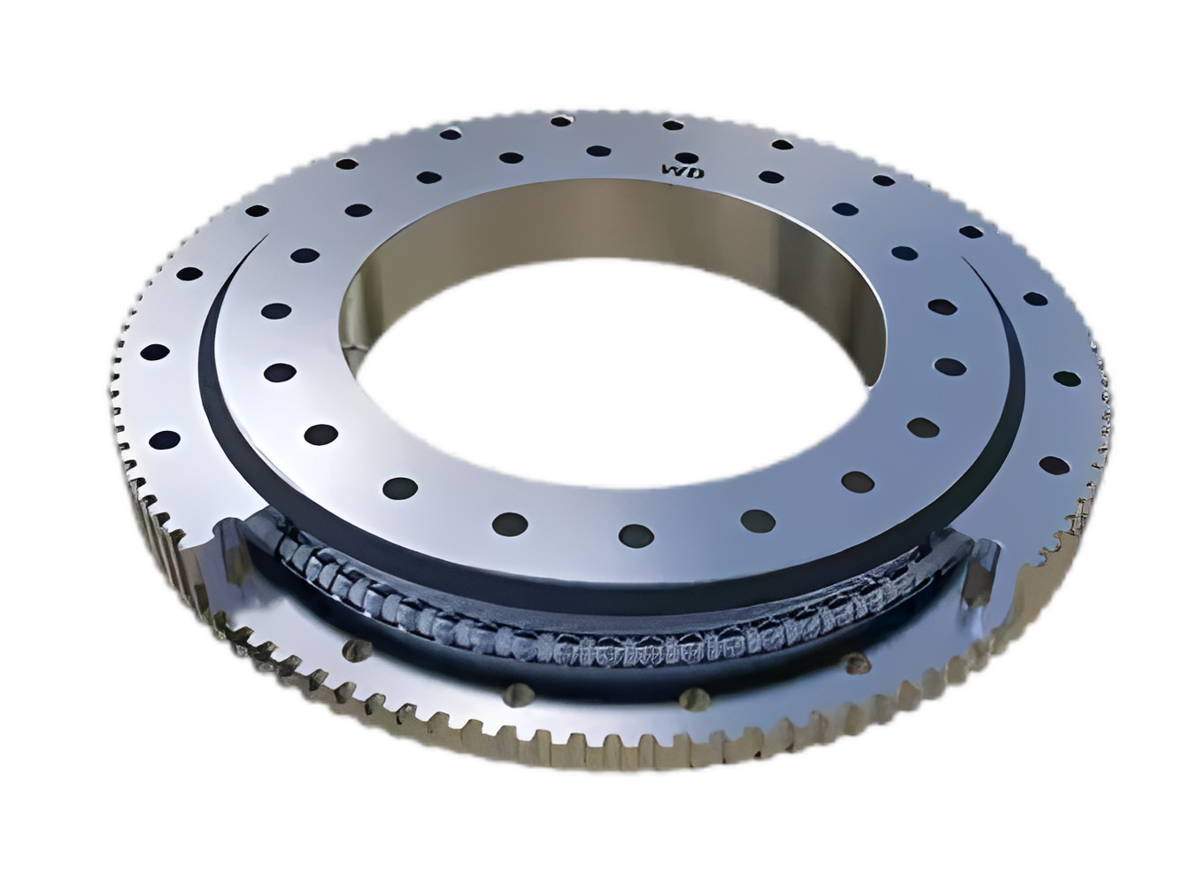
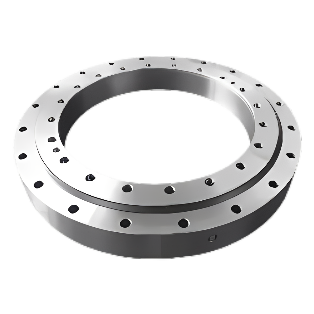
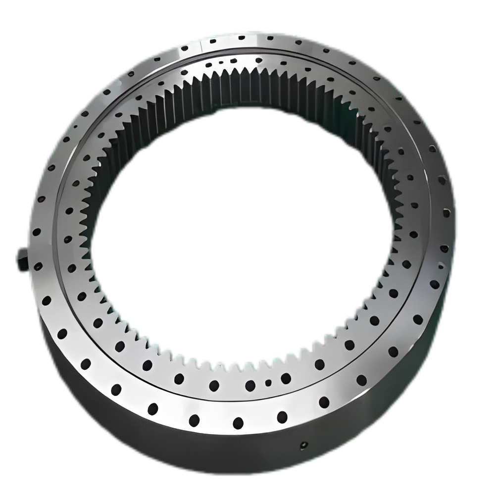
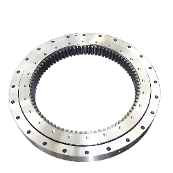
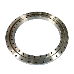
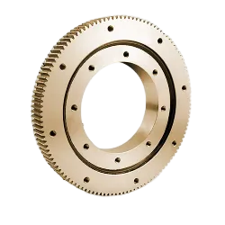
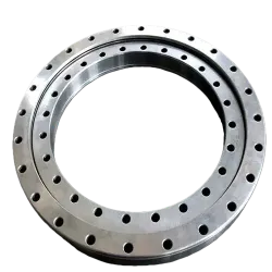
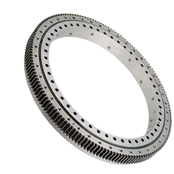
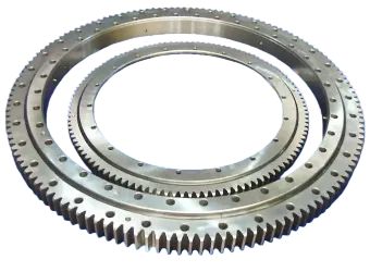
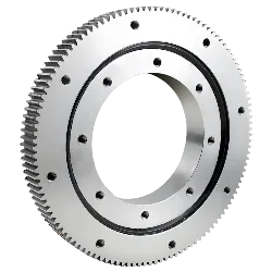
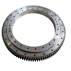
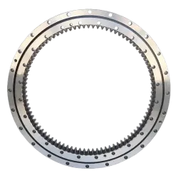
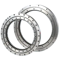
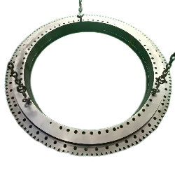

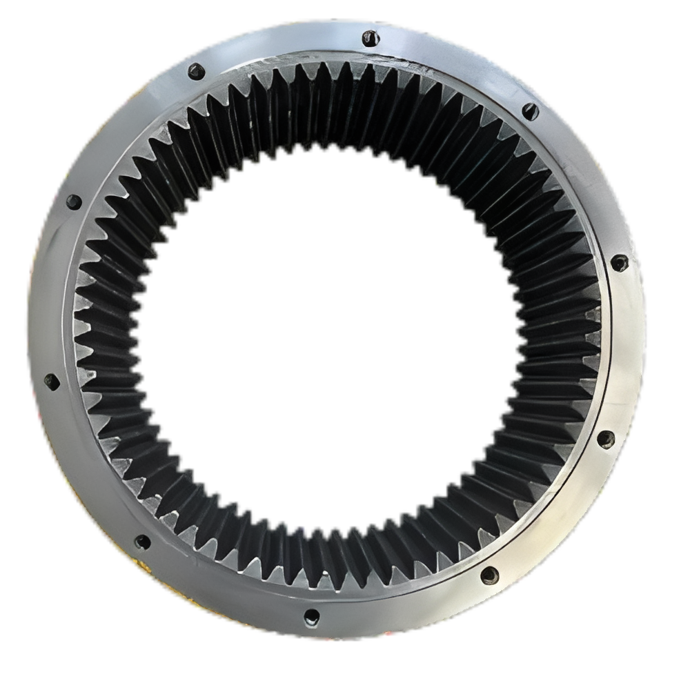
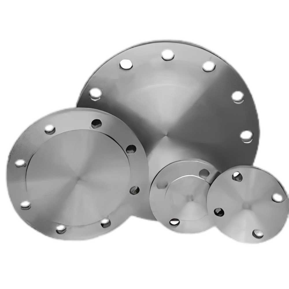
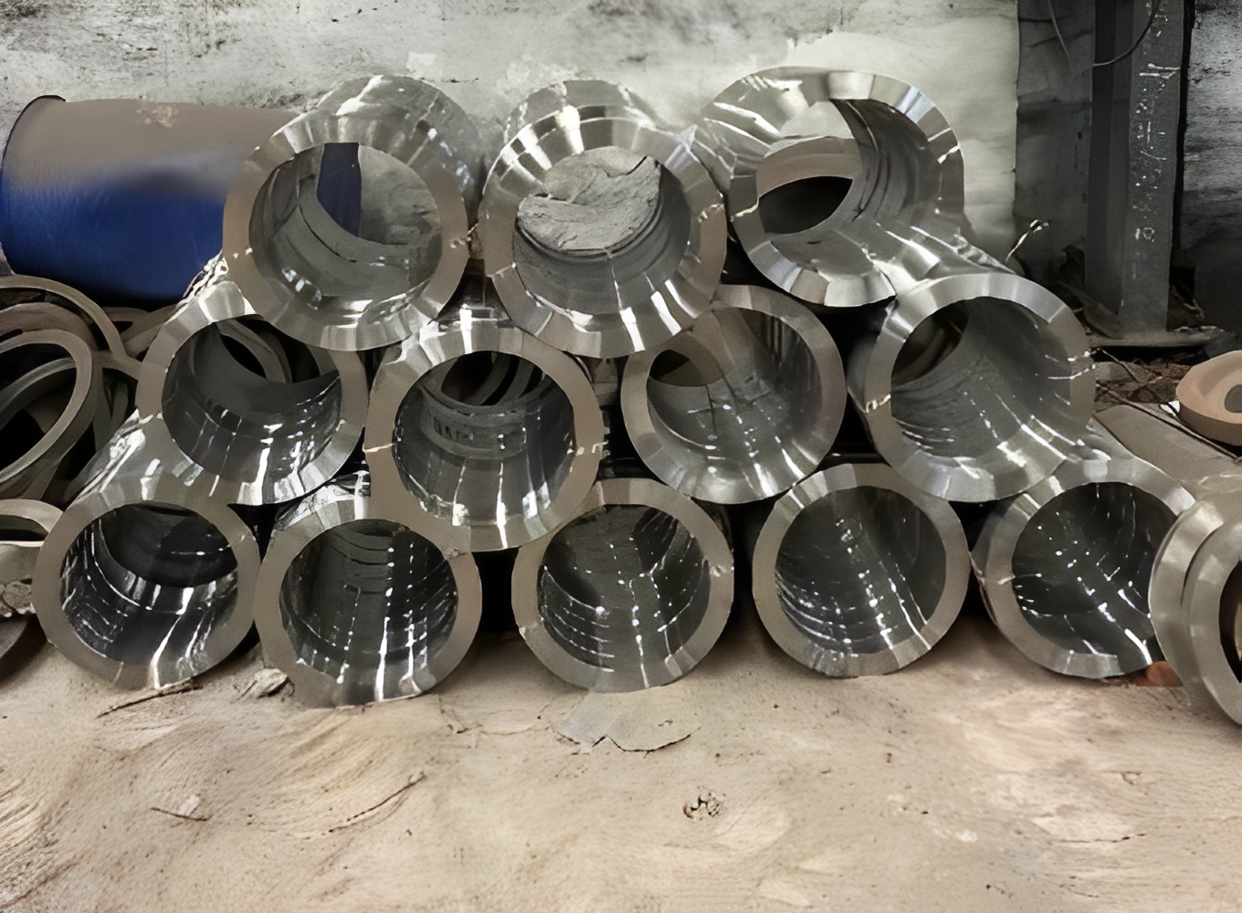
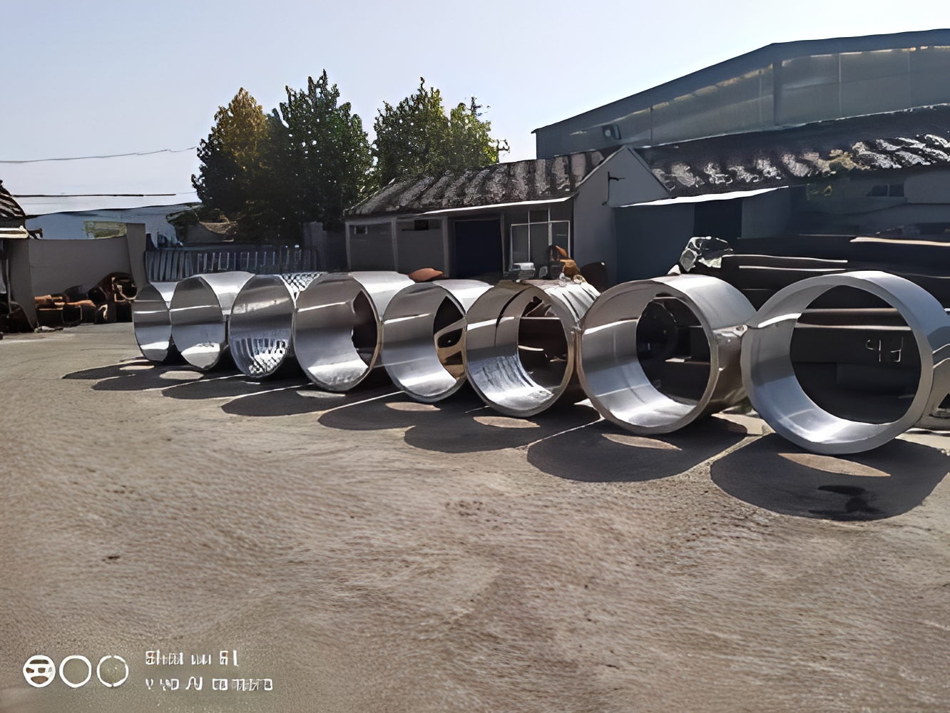

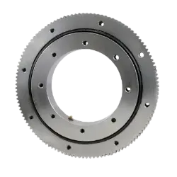
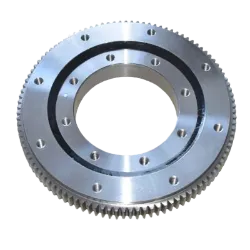
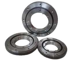
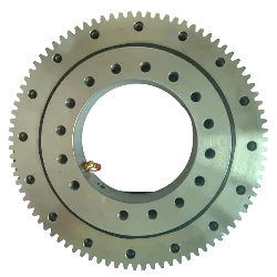
轻薄型系列回转支承
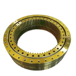
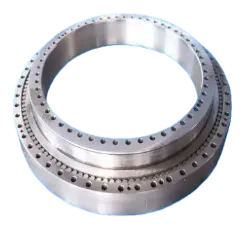
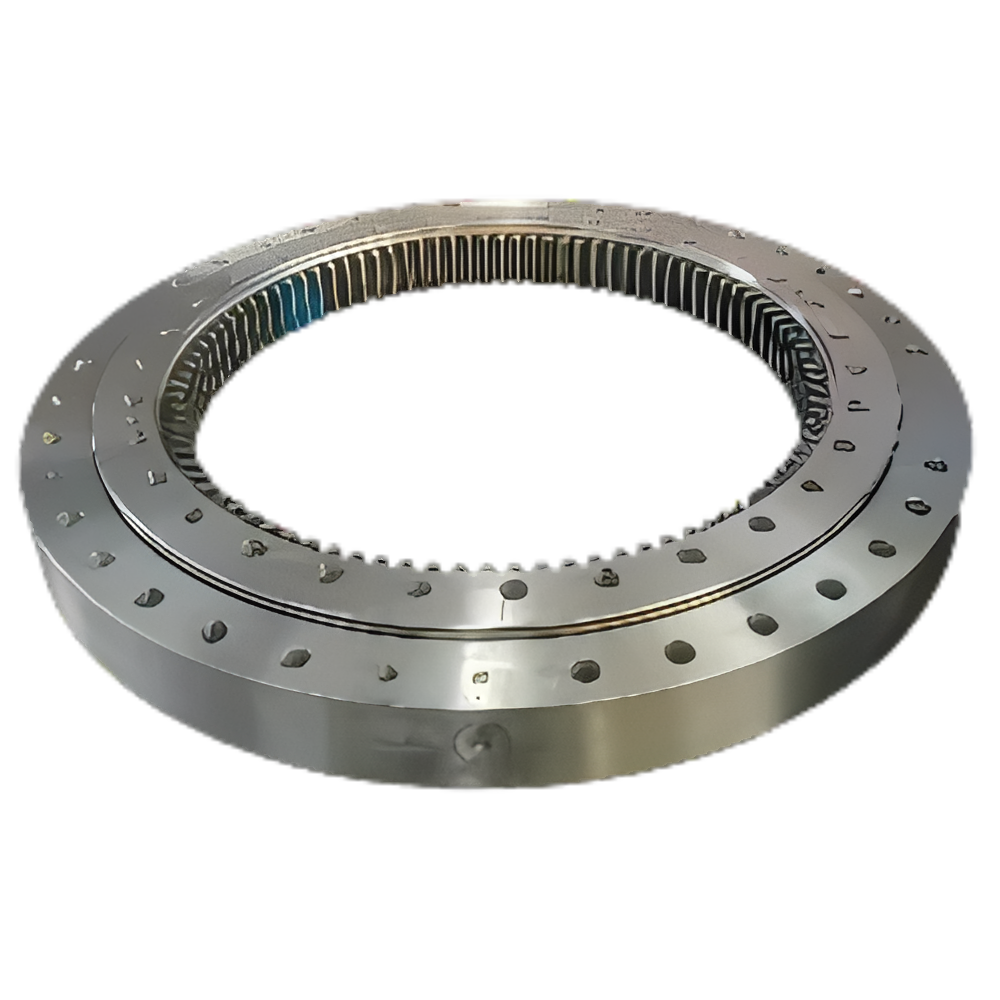
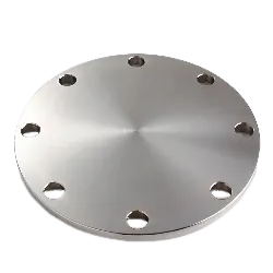
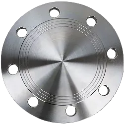
轻薄型系列回转支承的基本结构包括内圈、外圈、滚动体(滚珠或滚柱)、保持架和密封装置。与传统回转支承相比,轻薄型系列回转支承的截面高度较低,整体设计紧凑,重量轻、厚度薄、轻动灵活,广泛应用于食品机械、灌装机械、环保机械等。
联系我们
产品描述
注
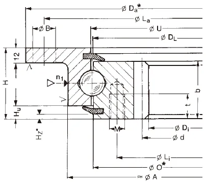
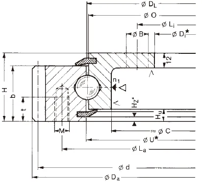
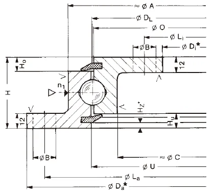
1、n1为润滑油孔数。油杯M10x1JB/T7940.1~JB/T7940.
2、根据应用情况用户可指定油孔位置,n- φ可改为螺纹孔,螺纹直径 M ,螺纹深度 2M
3、表内齿轮圆周力为最大圆周力,额定圆周力取其1/2。
4、“k”为削顶系数。
5、本样本中的规格为标准产品,内外径均为自由公差。若主机与回转支承有配合要求,请在合同或合同附件(如技术协议)中注明配合尺寸和精度。
6、表中所列为我公司常规产品,若有其他特殊要求,请与我公司联系
| model | weight | Overall Dimensions | Installation Dimensions | Structural Dimensions | Gear Parameters | Gear Tangential Force | Axial Clearance | Radial Clearance | |||||||||||||||||
| D | de | H | D1 | D2 | na | Φ | M | t | D3 | d1 | H1 | H2 | Hu | Ho | d | m | z | k.m | b | Allowable Tangential Force | Maximum Allowable Tangential Force | ||||
| YQ-061.20.0414 | 31 | 504 | 342 | 56 | 455 | 368 | 20/24 | 13.5 | 12 | 20 | 412.5 | 415.5 | 45.5 | 45.5 | 10.5 | 10.5 | 495 | 5 | 99 | -0.5 | 45.5 | 11.75 | 23.5 | ≤ 0.28 | ≤ 0.24 |
| YQ-061.20.0544 | 43 | 640.8 | 472 | 56 | 585 | 498 | 28/32 | 13.5 | 12 | 20 | 542.5 | 545.5 | 45.5 | 45.5 | 10.5 | 10.5 | 630 | 6 | 105 | -0.6 | 45.5 | 14.2 | 28.4 | ≤ 0.30 | ≤ 0.26 |
| YQ-061.20.0644 | 52 | 742.8 | 572 | 56 | 685 | 598 | 32/36 | 13.5 | 12 | 20 | 642.5 | 645.5 | 45.5 | 45.5 | 10.5 | 10.5 | 732 | 6 | 122 | -0.6 | 45.5 | 14.2 | 28.4 | ≤ 0.30 | ≤ 0.26 |
| YQ-061.20.0744 | 59 | 838.8 | 672 | 56 | 785 | 698 | 36/40 | 13.5 | 12 | 20 | 742.5 | 745.5 | 45.5 | 45.5 | 10.5 | 10.5 | 858 | 6 | 138 | -0.6 | 45.5 | 14.2 | 28.4 | ≤ 0.30 | ≤ 0.26 |
| YQ-061.20.0844 | 71 | 950.4 | 772 | 56 | 885 | 798 | 38/40 | 13.5 | 12 | 20 | 842.5 | 845.5 | 45.5 | 45.5 | 10.5 | 10.5 | 936 | 8 | 117 | -0.8 | 45.5 | 18.93 | 37.86 | ≤ 0.30 | ≤ 0.26 |
| YQ-061.20.0944 | 77 | 1046.4 | 872 | 56 | 985 | 898 | 40/44 | 13.5 | 12 | 20 | 942.5 | 945.5 | 45.5 | 45.5 | 10.5 | 10.5 | 1032 | 8 | 129 | -0.8 | 45.5 | 18.93 | 37.86 | ≤ 0.30 | ≤ 0.26 |
| YQ-061.20.1094 | 91 | 1198.4 | 1022 | 56 | 1135 | 1048 | 44/48 | 13.5 | 12 | 20 | 1092.5 | 1095.5 | 45.5 | 45.5 | 10.5 | 10.5 | 1184 | 8 | 148 | -0.8 | 45.5 | 18.93 | 37.86 | ≤ 0.30 | ≤ 0.26 |
| model | weight | Overall Dimensions | Installation Dimensions | Structural Dimensions | Gear Parameters | Allowable Tangential Force | Maximum Allowable Tangential Force | Axial Clearance | Radial Clearance | ||||||||||||||||||
| D | de | H | D1 | D2 | na | Φ/M | ni | Φ/M | t | n1 | D3 | d1 | A | C | Hu | Ho | d | m | z | b | k.m | ||||||
| YQ-231.20.0414 | 29.0 | 504 | 304 | 56 | 455 | 332 | 10 | M12 | 24 | 18 | 20 | 4 | 412.5 | 415.5 | 375 | 10.5 | 10.5 | 495 | 5 | 99 | 45.5 | -0.5 | 11.75 | 23.50 | ≤ 0.5 | ≤ 0.5 | |
| YQ-231.20.0544 | 39.2 | 640.8 | 434 | 56 | 585 | 462 | 14 | M12 | 28 | 18 | 20 | 4 | 542.5 | 545.5 | 505 | 10.5 | 10.5 | 630 | 6 | 105 | 45.5 | -0.6 | 14.2 | 28.40 | ≤ 0.5 | ≤ 0.5 | |
| YQ-231.20.0644 | 47.2 | 742.8 | 534 | 56 | 685 | 562 | 16 | M12 | 32 | 18 | 20 | 4 | 642.5 | 645.5 | 605 | 10.5 | 10.5 | 732 | 6 | 122 | 45.5 | -0.6 | 14.2 | 28.40 | ≤ 0.5 | ≤ 0.5 | |
| YQ-231.20.0744 | 53.1 | 838.8 | 634 | 56 | 785 | 662 | 18 | M12 | 32 | 18 | 20 | 4 | 742.5 | 745.5 | 705 | 10.5 | 10.5 | 828 | 6 | 138 | 45.5 | -0.6 | 14.2 | 28.40 | ≤ 0.5 | ≤ 0.5 | |
| YQ-231.20.0844 | 64.7 | 950.4 | 734 | 56 | 885 | 762 | 18 | M12 | 36 | 18 | 20 | 4 | 842.5 | 845.5 | 805 | 10.5 | 10.5 | 936 | 8 | 117 | 45.5 | -0.8 | 18.93 | 37.86 | ≤ 0.5 | ≤ 0.5 | |
| YQ-231.20.0944 | 69.1 | 1046.4 | 834 | 56 | 985 | 862 | 20 | M12 | 40 | 18 | 20 | 4 | 942.5 | 945.5 | 905 | 10.5 | 10.5 | 1032 | 8 | 129 | 45.5 | -0.8 | 18.93 | 37.86 | ≤ 0.5 | ≤ 0.5 | |
| YQ-231.20.1094 | 82.5 | 1198.4 | 984 | 56 | 1135 | 1012 | 22 | M12 | 40 | 18 | 20 | 4 | 1092.5 | 1095.5 | 1055 | 10.5 | 10.5 | 1184 | 8 | 148 | 45.5 | -0.8 | 18.93 | 37.86 | ≤ 0.5 | ≤ 0.5 | |
| NO. | Basic Model | Overall Dimensions | Installation Dimensions | Structure Size | Gear Parameters | Parameters of Internal Gears | Parameters of External Gears | |||||||||||||||
| Non-gear type DL(mm) | External gear type DL(mm) | Internal gear type DL(mm) | D | d | H | D₁ | D₂ | n | φ | n₁ | D₃ | d₁ | H₁ | h | b | X | m | De | Z | De | Z | |
| mm | mm | mm | mm | mm | mm | |||||||||||||||||
| 1 | 010.20.200 | 011.20.200 | - | 280 | 120 | 60 | 248 | 152 | 12 | 16 | 2 | 201 | 199 | 50 | 10 | 40 | 0 | 3 | 300 | 98 | - | - |
| 2 | 010.20.224 | 011.20.224 | - | 304 | 144 | 60 | 272 | 176 | 12 | 16 | 2 | 225 | 223 | 50 | 10 | 40 | 0 | 3 | 321 | 105 | - | - |
| 3 | 010.20.250 | 011.20.250 | - | 330 | 170 | 60 | 298 | 202 | 18 | 16 | 2 | 251 | 249 | 50 | 10 | 40 | 0 | 4 | 352 | 86 | - | - |
| 4 | 010.20.280 | 011.20.280 | - | 360 | 200 | 60 | 328 | 232 | 18 | 16 | 2 | 281 | 279 | 50 | 10 | 40 | 0 | 4 | 384 | 94 | - | - |
| 5 | 010.25.315 | 011.25.315 | 013.25.315 | 408 | 222 | 70 | 372 | 258 | 20 | 18 | 2 | 316 | 314 | 60 | 10 | 50 | 0 | 5 | 435 | 85 | 190 | 40 |
| 6 | 010.25.355 | 011.25.355 | 013.25.355 | 448 | 262 | 70 | 412 | 298 | 20 | 18 | 2 | 356 | 354 | 60 | 10 | 50 | 0 | 5 | 475 | 93 | 235 | 49 |
| 7 | 010.25.400 | 011.25.400 | 013.25.400 | 493 | 307 | 70 | 457 | 343 | 24 | 18 | 2 | 401 | 399 | 60 | 10 | 50 | 0 | 6 | 528 | 86 | 276 | 48 |
| 8 | 010.25.450 | 011.25.450 | 013.25.450 | 543 | 357 | 70 | 507 | 393 | 24 | 18 | 2 | 451 | 449 | 60 | 10 | 50 | 0 | 6 | 576 | 94 | 324 | 56 |